|
LTCC LAB Made in the USA |
||||||||||||||||||||||||||||||||||||||||||||||||||
| Home |
LTCC - Low Temperature Co-fired Ceramic, LTCClab offers prototype and manufacturing of LTCC (Low Temperature Co-fired Ceramic), Thick film printing, ceramic substrates. Typical LTCC design rules for LTCC
LTCC Green and fired tape thickness.
LTCC- Low Temperature Co-fired Ceramic parameters LTCC Dielectric constant @1 MHz 7.8 DF (Dissipation Factor) @ 10 MHz 0.15% I R (Insulation Resistance) @ 100 V DC > 1012 Meg ohms Ceramic breakdown Voltage V/25µm > 1000V LTCC Shrinkage X, Y 12.2%, Z 15% Thermal expansion of LTCC (25°C-300°C) 5.8ppm/°C Typical LTCC via diameter is 0.006" via cap 0.009" Line width 0.006", line space 0.006" Cofired inner layer conductor 100% Silver (Ag). Cofired top layer conductor Pd/Ag, Solderable termination, or Gold. Typical Design Rules for LTCC.
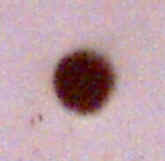
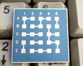
LTCC green tape with 4 mils via (X200) (Recommended 6 mils via) LTCC R1 - 0.006" line and 0.006" space between the lines. LTCC R2 - 0.008" Space -Via cap to line and via cap to via cap (Recommended 0.006" via)
LTCC R3 - 0.006" Via to 0.006" line connection (Recommended 0.006" via)
LTCC R4 - 0.008" via cap to via cap (Recommended 0.006" via)
LTCC R5 - Planes, 0.006" grid line and 0.012" space between the line
LTCC R6 - 0.012" space between line to LTCC edge and 0.014" via pad to LTCC edge (Recommended 0.006" via)
Low Temperature Co-fired Ceramic (LTCC) LTCClab offers prototype and manufacturing of LTCC (Low Temperature Co-fired Ceramic), Thick film printing, ceramics substrates, LTCC Ceramic Chip Capacitors, LTCC Multilayer ceramic chip capacitors (MLCC) Single layer ceramic chip capacitors (SLCC). Low Temperature Cofired Ceramic (LTCC) Chip Resistors. Multi layer substrate & packaging technology for a wide range of applications. The Low Temperature Co-fired Ceramic (LTCC) materials systems offer the highest performance packaging solutions for high-frequency devices in a wide variety of wireless, telecommunication, microwave, automotive, professional electronics, LTCC Bluetooth, Antenna Module, Transmitter, Power Amplifier, Filter Component, Duplexer Switch, and other applications. LTCClab offers prototype and manufacturing of LTCC (Low Temperature Co-fired Ceramic), Thick film printing, ceramics substrates, LTCC Ceramic Chip Capacitors, LTCC Multilayer ceramic chip capacitors (MLCC), Single layer ceramic chip capacitors (SLCC), Low Temperature Cofired Ceramic (LTCC) Chip Resistors. For LTCC, Thick film printing, chip Capacitors, chip Resistors, or info, please Contact LTCClab
|
|||||||||||||||||||||||||||||||||||||||||||||||||